Hacked Together Flight Yoke - Part 1
Building a Flight Yoke From Junk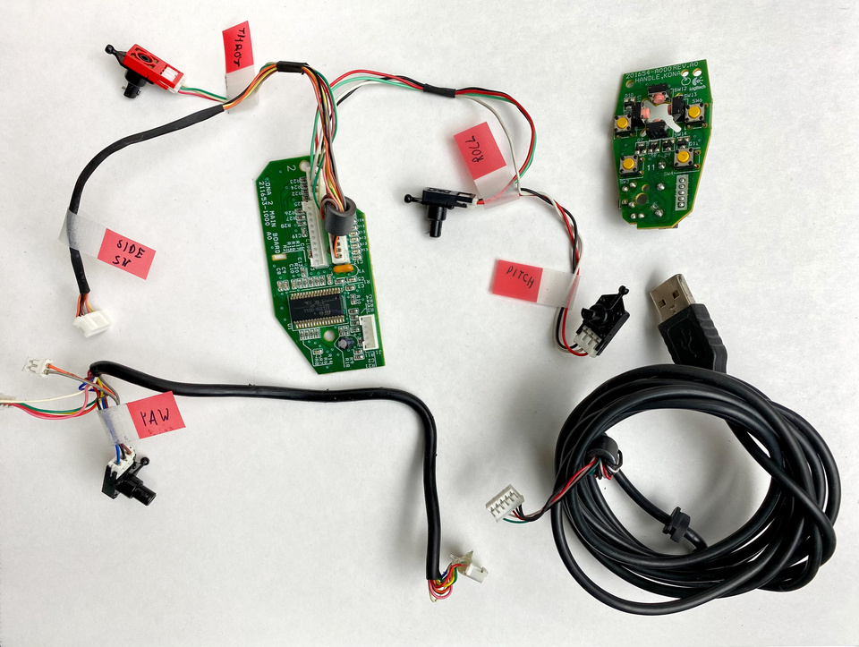
Flight Simulators are Cool. Hardware is Expensive.
All of the tankers flying around lately reminded me that I like airplanes, and flight simulators are fun. A while back I bought a Logitech Extreme 3D Pro joystick off of eBay, but it's kind of worn out and floppy and overall not enjoyable to use. A proper USB flight yoke is pretty expensive, so why not resurrect this joystick?
Disassembly
First, let's take the thing apart. Pictured above, there's not a whole lot inside of it. There's a main board that sends some stuff to the computer via USB, and a bunch of momentary switches and potentiometers (or encoders, but I doubt that, and it doesn't matter for this project).
Planning
Next, some innards. I figure this whole thing can sit in a wooden box, and I can design that later. 3D printer parts are cheap-ish now that they're so popular, so I figured I could make the pitch axis with some 8mm rods and LM8UU linear bearings. So far we're about $20 deep. I'm not sure what to do about the roll axis yet, but it seems like that's straightforward. I figured I'd need some sort of carriage for the rest of the stuff, so a very rudimentary first draft with some orange big box store angle aluminum is looking something like this:
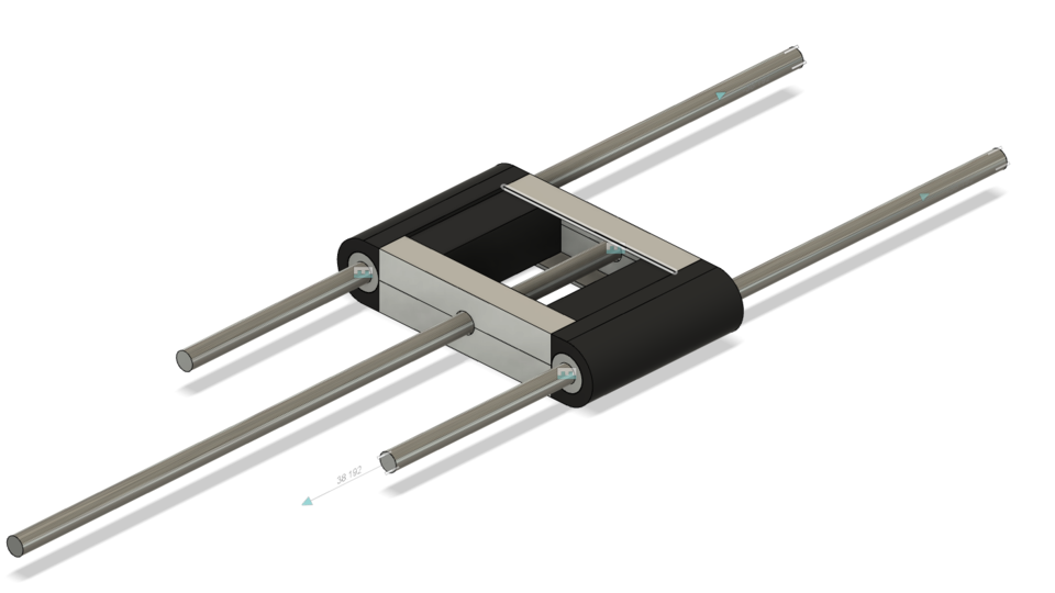
It's missing... many things, but this is the general idea. I'll need to add some way to center it (probably something with springs) and there needs to be... well everything with the linkage from the box to this carriage, so it knows where it is, and the entire roll axis is currently just a stick. Soon.
Gears
The first problem I ran into was converting this in-and-out motion on these linear bearings into rotational motion that the little potentiometers on the old junky joystick can use. I don't really know how to design levers, and that seems... fragile, so I didn't even bother.
Let's use some gears!
Unfortunately, I don't really know much about gears either, but I'm pretty sure you can 3D print them and I can do something with a rack and pinion to get the in-and-out into spinning.
After hours of this YouTube channel Antalz, I felt that I had a decent grasp on modelling the damn things and how they worked.
Sidenote: go check out these videos. They're super thorough and high quality, and exactly what I needed to design some gears for this project, and the guy only has ~800 followers as I write this.
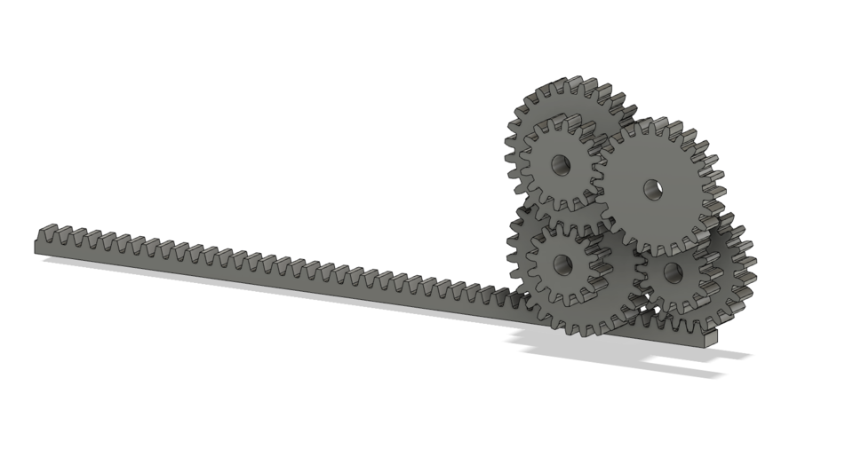
I needed to get from the rack down to the potentiometers range, which after measuring was about 120 degrees, or 1/3 of a turn. I also wanted to make this gear setup not take up much more range than the rods and linear bearings, so I wanted it to be compact. The result is a small gearbox that has 2, 2, and 1.5 ratios, and a pinion on the rack with a 1:2 ratio. I chose such a complex gearbox because my 3D printer sucks, so I wanted to keep the gear module as high as possible to give the printer a fighting chance. This is probably silly and I'll have to redesign it, but that's where we're at for now.
Next Steps
- I need to iterate on the gearbox. I think it could be smaller, and a lot of it is... wrong. The output gear needs a keyed shaft, which somehow I need to adapt to the potentiometer.
- I need to check if the microcontroller on the board actually reads the full range of the potentiometer. I didn't think about this at first, but the joystick, as manufactured, definitely doesn't have 120 degrees of motion on the pitch axis, and I don't know if that's taken care of by calibration, or limits burned into the microcontroller.
- After settling on a design for the gearbox, I need to some how glue it to the carriage shown earlier.
- I need to check if my 3D printer can actually print these gears, and see if they mesh relatively smoothly.
- Roll?
- Yaw??